Case
I have installed all the
prerequisites, now I want to start a new Visual Studio Project. Which project do I choose and which assemblies do I need to reference for a IoT project?
Solution
Below you find the basic code you need to send sensor data to the
Azure IoT Hub. The specific sensor code differs per sensor and will be posted in separate posts. Make sure to first install all
prerequisites.
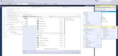
1) Blank App (Universal Windows)
Open Visual Studio 2015 and create a new project. We will be using C# as language. Under C#, Windows you will find the 'Blank App (Universal Windows)' project. Supply a ProjectName and Solution Name (also notice the checkbox for Source Control). Our project (and solution) is called Sensory.
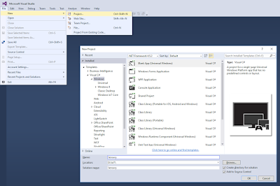 |
| Blank App (Universal Windows) |
When you create such project it will ask which version of Windows you want to use. Click on the
help link if you're not sure.
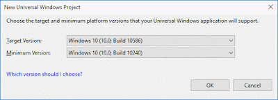 |
| Windows version |
2) Source Control
The next window will be about source control because of the checkbox in the previous step. We will be using Team Foundation Server (TFS) for source control. This is
recommended especially when you work in a team. You can either use your local TFS machine or use TFS online at
visualstudio.com. It's also possible to use third party source control software.
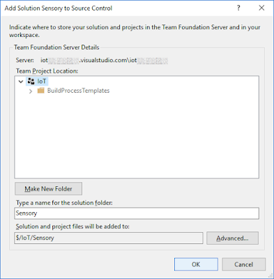 |
| TFS online |
3) Reference to Windows IoT Extensions for the UWP
A new blank project has been loaded. First we need a reference for IoT Extensions. Go to the Solution Explorer and right click on references and choose "Add Reference...". Then under Universal Windows / Extensions, locate "Windows IoT Extensions for the UWP". Sometimes you will find multiple versions. Make sure to choose the right one. We need version 10.0.10586.0.
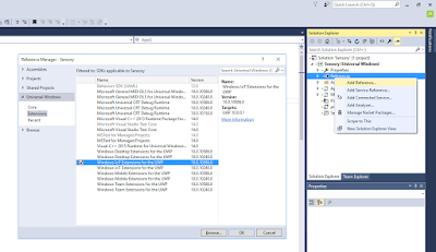 |
| Windows IoT Extensions for the UWP |
4) Add NuGet Packages for Azure
Because we want to connect to Azure, we need to add a NuGet for Microsoft.Azure.Devices.Client.PCL. Right click the project (not the solution) and choose "Manage NuGet Packages". Then go to Browse and search for "Microsoft.Azure.Devices.Client.PCL" and click on the Install button. When you're ready, a new reference appears in the Solution Explorer.
 |
| Add NuGet for Azure |
5) SensorMessage Class
For this project we have created a Sensor Message class to store the sensor values from one meassuring moment. Each x seconds/minutes we meassure for example the temperature and the illumination in a room. We store this in a SensorMessage object and then we are able to create a JSON message with these values and send this message to the
Azure IoT Hub.
Right click the project and choose 'Add', 'New Item...' and in the new window choose Class. Give it the name SensorMessage. Copy and past the code below to the new class. If you used a different project name then change the namespace from Sensory to your namespace name.
 |
| Add new class file |
//C# Code
using System;
using System.IO;
using System.Runtime.Serialization;
using System.Runtime.Serialization.Json;
using System.Text;

namespace Sensory
{
    [DataContract]
    public class SensorMessage
    {
        #region Properties with get and/or set
        [DataMember]
        private string sensorName;
        public string SensorName
        {
            get { return sensorName; }
        }

        [DataMember]
        private DateTime measurementTime;
        public DateTime MeasurementTime
        {
            get { return measurementTime; }
        }

        [DataMember]
        private decimal temperature;
        public decimal Temperature
        {
            get { return temperature; }
            set { temperature = value; }
        }

        [DataMember]
        private decimal humidity;
        public decimal Humidity
        {
            get { return humidity; }
            set { humidity = value; }
        }

        [DataMember]
        private decimal pressure;
        public decimal Pressure
        {
            get { return pressure; }
            set { pressure = value; }
        }

        [DataMember]
        private decimal altitude;
        public decimal Altitude
        {
            get { return altitude; }
            set { altitude = value; }
        }

        [DataMember]
        private decimal decibel;
        public decimal Decibel
        {
            get { return decibel; }
            set { decibel = value; }
        }

        [DataMember]
        private int doorOpen;
        public int DoorOpen
        {
            get { return doorOpen; }
            set { doorOpen = value; }
        }

        [DataMember]
        private int motion;
        public int Motion
        {
            get { return motion; }
            set { motion = value; }
        }

        [DataMember]
        private int vibration;
        public int Vibration
        {
            get { return vibration; }
            set { vibration = value; }
        }

        [DataMember]
        private decimal illumination;
        public decimal Illumination
        {
            get { return illumination; }
            set { illumination = value; }
        }
        #endregion

        #region Constructor method
        ///
        /// Creates SensorMessage object with default values
        /// Code should look something like:
        /// SensorMessage sensorMessage = new SensorMessage("mySensor");
        ///
        /// The name or unique code of your sensor
        public SensorMessage(string SensorName)
        {
            sensorName = SensorName;
            // measurementTime = DateTime.Now;
            // Fix for timezone / offset troubles
            // after serializing to JSON. Without
            // this it shows UTC time with offset
            measurementTime = DateTime.UtcNow.AddHours(TimeZone.CurrentTimeZone.GetUtcOffset(DateTime.Now).Hours);
            temperature = 0;
            humidity = 0;
            pressure = 0;
            altitude = 0;
            decibel = 0;
            doorOpen = 0;
            motion = 0;
            vibration = 0;
            illumination = 0;
        }
        #endregion

        #region ToJson method
        ///
        /// Extension method to convert object to JSON format
        /// It uses all properties with [DataMember] above it
        ///
        ///
        public string ToJson()
        {
            DataContractJsonSerializer ser = new DataContractJsonSerializer(typeof(SensorMessage));
            MemoryStream ms = new MemoryStream();
            ser.WriteObject(ms, this);
            string json = Encoding.UTF8.GetString(ms.ToArray(), 0, (int)ms.Length);

            return json;
        }
        #endregion
    }
}
5b) ToJson
The ToJson method in this class automatically returns a JSON message with all class properties that have [DataMember] above it. Also make sure to add [DataContract] above the class. It will generate the following message that can be read by the event Hub:
{"altitude":2.94,"decibel":7.43,"doorOpen":0,"humidity":93.97,"illumination":85.00, "measurementTime":"\/Date(1468490582115)\/","motion":0,"pressure":98.46, "sensorName":"Joost","temperature":89.49,"vibration":1}
Tip: try to keep the message as small as possible by using small columnnames or codes instead of large text values.
6) Main code
Locate the MainPage.xaml(.cs) file in the Solution Explorer and open the code behind it (the C# code). We have added some usings and methods which you need to add to your file. After that you can customize the code to your sensors/situation. In the following posts we will show you the sensor specific code for each sensor we will use in our IoT project.
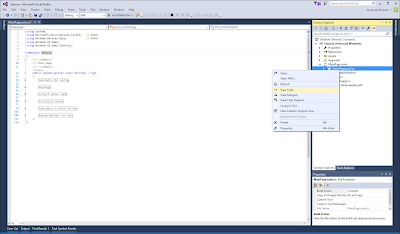 |
| MainPage.xaml.cs |
//C# Code
using System;
using Microsoft.Azure.Devices.Client;   // Added
using Windows.Devices.Gpio;             // Added
using Windows.UI.Xaml;
using Windows.UI.Xaml.Controls;

namespace Sensory
{
    ///
    /// Main page
    ///
    public sealed partial class MainPage : Page
    {
        #region Constants for config
        // GPIO PIN CONFIG
        const int PIN_DOORSENSOR = 4;

        // Azure IoT Hub connection string
        // Will be explained in next blogpost
        const string azureConnectionString = "HostName=xxxxxx.azure-devices.net;DeviceId=XXXXXXXX;SharedAccessKey=y1ANJwjTueyzCEBEAliy7MkOQHW5dOWiu6w79HcfvVc=";
        #endregion

        #region MainPage
        ///
        /// Method that execute on startup
        ///
        public MainPage()
        {
            this.InitializeComponent();

            // Initialize sensors
            InititializeDoorSensor();

            // Add timer event to collect and send
            // data each x seconds or minutes
            DispatcherTimer sensorTimer;
            sensorTimer = new DispatcherTimer();
            sensorTimer.Interval = TimeSpan.FromSeconds(60);
            sensorTimer.Tick += GetSensorData_Tick;
            sensorTimer.Start();
        }
        #endregion

        #region Collect sensor data
        // Method that is execute each x seconds
        // and collects the data from the sensors.
        // For this example it generates random data
        private void GetSensorData_Tick(object sender, object e)
        {
            // Create sensorMessage object and fill all
            // meassi=urements (with random data for now)
            SensorMessage sensorMessage = new SensorMessage("mySensor");
            sensorMessage.Illumination = randomDecimal();
            sensorMessage.Temperature = randomDecimal();
            sensorMessage.Humidity = randomDecimal();
            sensorMessage.Pressure = randomDecimal();
            sensorMessage.Altitude = randomDecimal();
            sensorMessage.Decibel = randomDecimal();
            sensorMessage.DoorOpen = randomInt(0.5);
            sensorMessage.Motion = randomInt(0.3);
            sensorMessage.Vibration = randomInt(0.1);

            // Send the data to the Azure IoT Hub
            SendMessage(sensorMessage.ToJson());
        }
        #endregion

        #region Initialize sensor
        // GPIO objects
        private GpioPin doorSensorPin;
        // Setup doorsensor
        private void InititializeDoorSensor()
        {
            // add sensor code
        }
        #endregion

        #region Send data to Azure IoT Hub
        // Object for sending data to azure
        private DeviceClient deviceClient = DeviceClient.CreateFromConnectionString(azureConnectionString);
        ///
        /// Sends JSON message to Azure IoT Hub
        ///
        /// The JSON message
        public async void SendMessage(string message)
        {
            // Send message to an IoT Hub using IoT Hub SDK
            try
            {
                var content = new Microsoft.Azure.Devices.Client.Message(System.Text.Encoding.UTF8.GetBytes(message));
                await deviceClient.SendEventAsync(content);

#if DEBUG   // DEBUG INFO
                System.Diagnostics.Debug.WriteLine("Message Sent: {0}", message, null);
#endif
            }
            catch (Exception e)
            {
#if DEBUG   // DEBUG INFO
                System.Diagnostics.Debug.WriteLine("Exception when sending message:" + e.Message);
#endif
            }
        }
        #endregion

        #region Random Methods for test
        private int randomInt(double chance)
        {
            // Make sure each call returns a random number
            Thread.Sleep(1);

            Random test = new Random(DateTime.Now.Millisecond);

            if (test.NextDouble() >= chance)
            {
                return 1;
            }
            else
            {
                return 0;
            }
        }

        private decimal randomDecimal()
        {
            // Make sure each call returns a random number
            Thread.Sleep(1);

            Random test = new Random(DateTime.Now.Millisecond);
            return Math.Round(Convert.ToDecimal(test.NextDouble() * 100), 2);
        }
        #endregion
    }
}
6b) Random
The two random methods are temporary methods that return random data to test the application without the sensor specific code. This allows us to continue in parallel with the
Azure IoT Hub, Stream Analytics and PowerBI.
7) Active Solution Platform
For building this project we need to switch to ARM (Acorn RISC Machine) instead of x86/x64. This is the processor architecture used on machines like the Raspberry Pi.
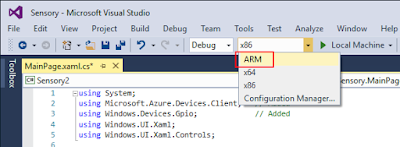 |
| Switching Solution Platform to ARM |
8) Deploying to Raspberry Pi
When your project is ready you can deploy it to your Raspberry Pi for debugging and testing. First you have to get the IP address of the Raspberry Pi device. The Windows 10 IoT Core Dashboard application is a good way to find your device(s). You will get the best result using a wired connection. When using WiFi the list below will sometimes stay empty.
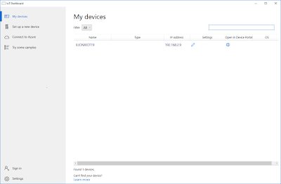 |
| Windows 10 IoT Core Dashboard |
You can also use Visual Studio to find the device. Go to the properties of your project. Then go to the Debug page and click on the Find button. On this page you can select the name or IP address from your device for deploying your code.
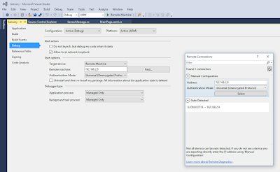 |
| Find your IoT device |
Now you can use the green start button to deploy and debug your code on the remote device, but the first time you first need to select 'Remote Machine'. The first deployment could take a couple of minutes!
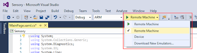 |
| Start debugging |
Now watch the output window in Visual Studio to see if your program is working. It's good to add a lot of Debug.WriteLine rows in de beginning to see whether everything works.
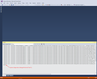 |
| Debug output |
Conclusion
A lot of work to start with, but if the basic works you can start customizing the code for your sensors. You will need some patience because finding your Raspberry Pi sometimes need a couple of attemps (wired is more ofted successful) and the first deployment takes a couple of minutes. Don't worry if it takes 3 minutes.
In the next few blogposts we will show the specific sensor code and show you how to create the
Azure IoT Hub connection string.


